Written by
Halkwinds Editorial Team
Halkwinds Research & Editorial
Warehouse and Factory Robotics: Integration Architecture for Automated Production Lines
A reference architecture for fleet management, PLC and robot controller integration, safety systems, and mixed human-robot orchestration on the production floor
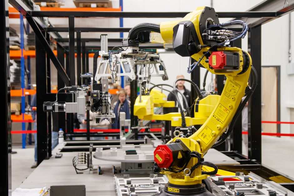
Most manufacturers do not fail at robotics because the robot arm or the AMR underperforms. They fail at the seams — the software layer that has to make a fleet of AMRs, a dozen robot controllers, a safety PLC, a WMS, and a floor full of human operators behave as one coherent system. That seam is an architecture problem, not a hardware problem, and it is where most integration budgets and timelines actually get spent.
This article lays out a practical reference architecture for integrating industrial robots and AMRs into production lines: fleet management above individual robot controllers, PLC and robot controller integration patterns, safety systems as an independent deterministic layer, and orchestration of workflows where humans and robots share the same task queue.
Table of Contents
- Why Robotics Integration Architecture Matters Now
- Reference Architecture: From Robot Controller to MES
- Fleet Management for AMRs: Traffic, Task Allocation, and Fallback
- PLC and Robot Controller Integration Patterns
- Safety Systems as a First-Class Architectural Layer
- Orchestrating Mixed Human-Robot Workflows
- Data, Observability, and the Maintenance Connection
- Common Integration Failure Modes and How to Avoid Them
Key Takeaways
- In our experience, once a floor runs more than roughly 8 to 10 concurrent AMRs, point-to-point PLC integration stops scaling and a dedicated fleet management layer becomes necessary for traffic arbitration and task allocation.
- Safety systems — e-stops, light curtains, safety PLCs — typically run on a certified safety network (PROFIsafe or CIP Safety) that is architecturally independent from orchestration middleware, so a fleet manager outage can never compromise a safety interlock.
- Mixed human-robot cells commonly deliver their biggest ROI by reducing cycle time variance rather than average cycle time, which changes how the business case should be modeled.
- In our experience, most robotics integration delays trace back to mismatches at the controller-to-MES/WMS interface layer, not to the robots or AMRs themselves.
Why Robotics Integration Architecture Matters Now
Robot and AMR deployments have moved past the single-cell pilot stage. A typical mid-size manufacturer today is integrating a mixed fleet — fixed robot arms from two or three vendors, AMRs from another, conveyor and PLC-controlled stations, and a WMS or MES expecting clean, timely status updates from all of it. Each vendor ships its own controller, its own protocol quirks, and its own notion of what a task or a fault looks like.
Without a deliberate integration architecture, teams end up hand-wiring point-to-point connections between every controller and every downstream system. That works for a pilot with two robots but becomes unmanageable, and risky, once the floor has real production volume. The decisions made early — where the fleet manager sits, how safety is isolated, how PLCs talk to robot controllers — determine whether the tenth robot added to the line takes a week or a quarter.
Reference Architecture: From Robot Controller to MES
A workable reference architecture separates concerns into distinct layers rather than letting any single system do everything. At the bottom sits the equipment layer: robot controllers, PLCs, safety controllers, and AMR onboard computers, each running its own real-time control loop. Above that sits an integration and fleet orchestration layer — often built on an industrial message broker or OPC UA server — that normalizes heterogeneous vendor protocols into a consistent internal model of tasks, states, and events.
Above orchestration sits the execution systems layer: MES for production sequencing, WMS for inventory and pick logistics, and increasingly a dedicated robot fleet manager arbitrating between multiple AMR vendors. At the top sits analytics and monitoring, consuming events from every layer below for dashboards and predictive maintenance models. Keeping these layers cleanly separated is what lets a plant swap a robot vendor or add a new AMR fleet without re-architecting the whole stack.
Fleet Management for AMRs: Traffic, Task Allocation, and Fallback
AMR fleet management is fundamentally a distributed systems problem wearing an industrial costume. The fleet manager solves traffic arbitration — which robot gets right of way at a shared intersection — task allocation, deciding which robot is best positioned for the next pick, and battery management so robots do not go dark mid-task.
Multi-vendor fleets add a harder problem: interoperability. The VDA 5050 standard has become a common baseline for master-control-to-AMR communication across vendors, and architecting around it, rather than a single vendor's proprietary API, is typically the safer long-term bet. Just as important is the fallback path: what happens when a robot loses connectivity, a battery drops below threshold mid-route, or the fleet manager itself goes down. In our experience, plants that design explicit degraded-mode behavior — robots parking safely, tasks re-queuing automatically, a clear manual-override path — recover from incidents in minutes rather than shutting down a line for hours.
PLC and Robot Controller Integration Patterns
PLC-to-robot integration is where a lot of otherwise solid architectures quietly break, because the two worlds speak different dialects of real time. PLCs operate on deterministic scan cycles and expect discrete I/O or fieldbus signals (EtherCAT, PROFINET, EtherNet/IP). Robot controllers run their own motion-planning cycle and expose a richer state model over an industrial protocol or vendor SDK. The integration layer must translate between a PLC's bit-level handshake (part-ready, cycle-start, fault) and a robot controller's program-and-status model without introducing timing ambiguity.
The pattern that holds up well in practice is keeping discrete, time-critical handshakes — start, done, fault, e-stop status — on hardwired or fieldbus I/O directly between the PLC and robot controller, while routing non-time-critical data through the integration layer over OPC UA or MQTT. This keeps the cycle-critical path short and deterministic while still giving the MES and analytics layers the visibility they need.
Safety Systems as a First-Class Architectural Layer
Safety cannot be an afterthought bolted onto the orchestration layer, and it should never share a failure domain with it. Light curtains, e-stops, safety mats, and area scanners should terminate at a safety-rated controller running a certified protocol — PROFIsafe over PROFINET or CIP Safety over EtherNet/IP are common choices — operating independently of the fleet manager, the MES, and any general-purpose middleware.
The rule worth enforcing is that a safety stop must be achievable even if every non-safety-rated system on the floor is unreachable. The safety PLC should directly command the drive- or contactor-level cutoff, never relaying a stop command through a fleet manager over a best-effort network. For AMRs, this extends to onboard safety-rated LIDAR and the robot's own certified safety controller, which must stop the vehicle without a round trip to the fleet server. Non-safety systems can observe safety events for logging, but must never sit in the control path itself.
Orchestrating Mixed Human-Robot Workflows
Once robots and people share a work cell or an aisle, the orchestration problem shifts from pure machine coordination to workflow choreography. A task orchestration layer needs to understand which steps are robot-only, which are human-only, and which are handoffs, and it needs a way to represent an operator's current state (available, on-task, on-break) with the same rigor it represents a robot's state.
The most common failure we see is treating the human as an implicit resource the system assumes is always ready, producing workflows that look fine in simulation and stall on the real floor. A better pattern gives operators a lightweight interface — a handheld scanner, a tablet, or a pendant — to explicitly signal readiness or flag an exception, feeding that signal into the same task queue the robots draw from. Cycle time variance, not just average throughput, is usually the metric that improves most, because predictable handoffs reduce idle time on both sides of the human-robot boundary.
Data, Observability, and the Maintenance Connection
Every layer of this architecture generates telemetry — robot cycle times and fault codes, AMR battery and route data, PLC I/O states, safety event logs, and operator task completions. Centralizing that telemetry, typically through a historian or time-series database, is what makes the stack observable rather than a black box.
This is also where robotics integration architecture connects to predictive maintenance. Robot joint torque anomalies, AMR motor current drift, and PLC fault frequency are leading indicators that, fed into a condition-monitoring pipeline, let teams schedule maintenance before an unplanned outage mid-shift. We covered the ML and IoT architecture for that pipeline in our predictive maintenance architecture guide, and the two architectures should share the same telemetry backbone by design.
Common Integration Failure Modes and How to Avoid Them
Three failure patterns show up repeatedly. The first is protocol sprawl: every new robot or AMR vendor gets its own point-to-point connection to the MES, and within two years nobody fully understands the dependency map. The fix is enforcing that all production-system integration goes through the normalized orchestration layer, even when a direct connection would be faster initially.
The second is under-specified degraded-mode behavior, where the system works until a robot loses connectivity or a sensor goes offline, and the line stalls because no one designed what should happen next. The fix is treating fallback paths as first-class requirements during design, not something discovered during commissioning. The third, covered above, bears repeating because it carries the highest consequence: a safety interlock must never depend on a non-safety-rated system to function.
Getting robotics integration architecture right is ultimately about discipline in layering — keeping safety independent, keeping fleet management above individual controllers rather than replaced by point-to-point wiring, and keeping the telemetry backbone shared across orchestration and maintenance use cases. If you are scoping a robotics integration project and want a second opinion on the architecture before committing engineering time to it, reach out to our team to talk through your specific line configuration.
Frequently Asked Questions
What is the difference between a robot controller and a fleet management system?
A robot controller manages the real-time motion and I/O of a single robot or AMR. A fleet management system sits above multiple controllers, arbitrating traffic, allocating tasks, and managing charging across an entire fleet, typically spanning multiple vendors.
Which protocols matter most for AMR fleet interoperability?
VDA 5050 has become the common baseline for master-control-to-AMR communication. For robot arms and PLCs, OPC UA and MQTT are typically used at the orchestration layer, while PROFINET, EtherNet/IP, or EtherCAT handle time-critical PLC-to-controller signals.
Can safety systems and fleet orchestration share the same network?
They can share physical infrastructure, but the safety logic itself must run on a certified safety protocol and remain functionally independent, so an orchestration or network outage never disables a safety interlock.
How do mixed human-robot workflows affect production line design?
They require the task orchestration layer to model operator availability and handoffs with the same rigor as robot state, typically through a lightweight interface for operators to signal readiness or exceptions.
Where should a manufacturer start when architecting a robotics integration project?
Start by mapping the layers — equipment, orchestration, execution systems, analytics — and deciding early where fleet management and safety will sit, since those decisions are hardest to retrofit later.
Explore Further